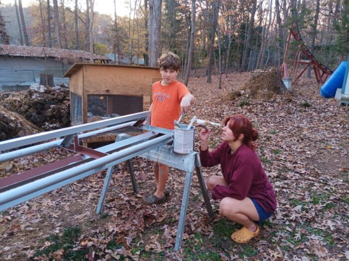
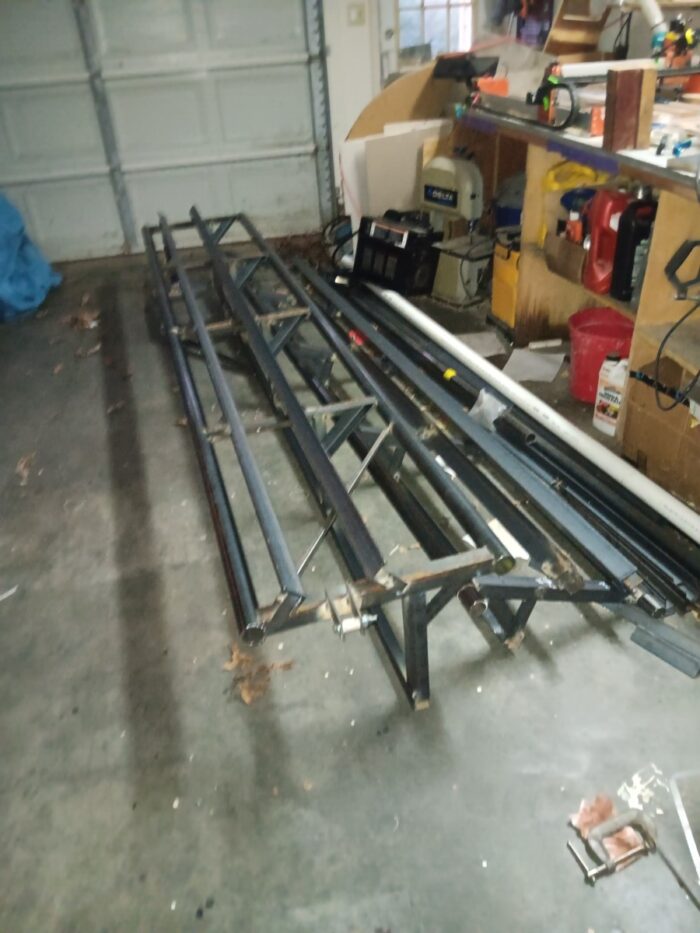
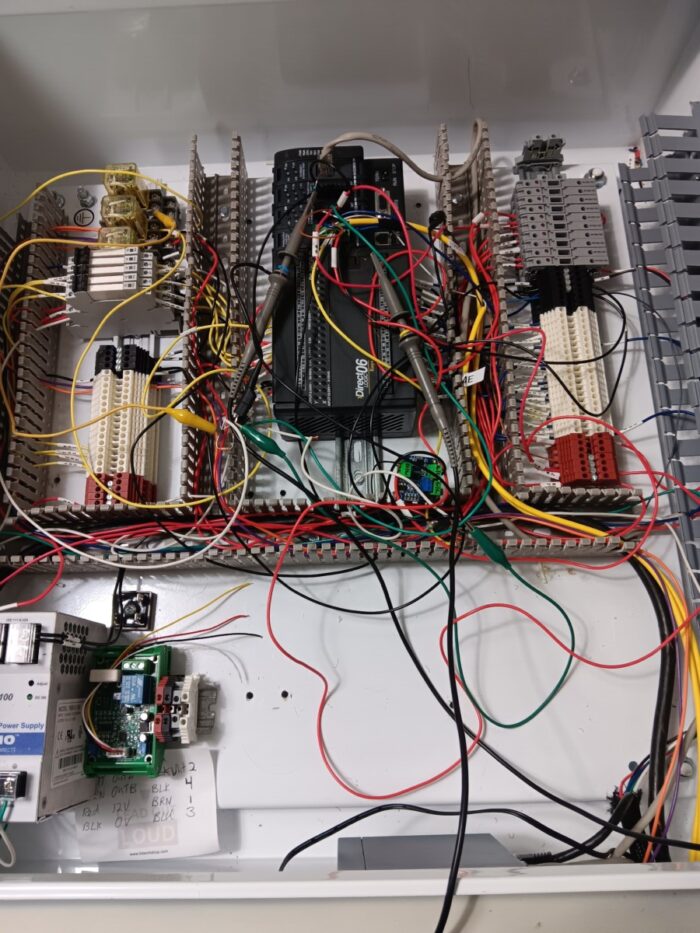
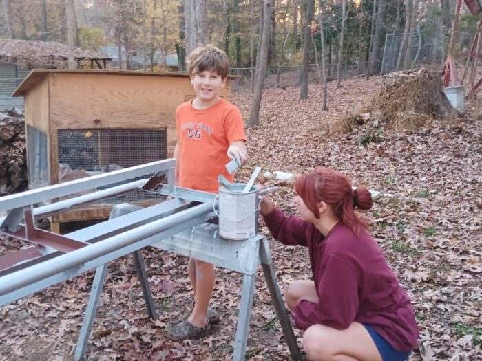
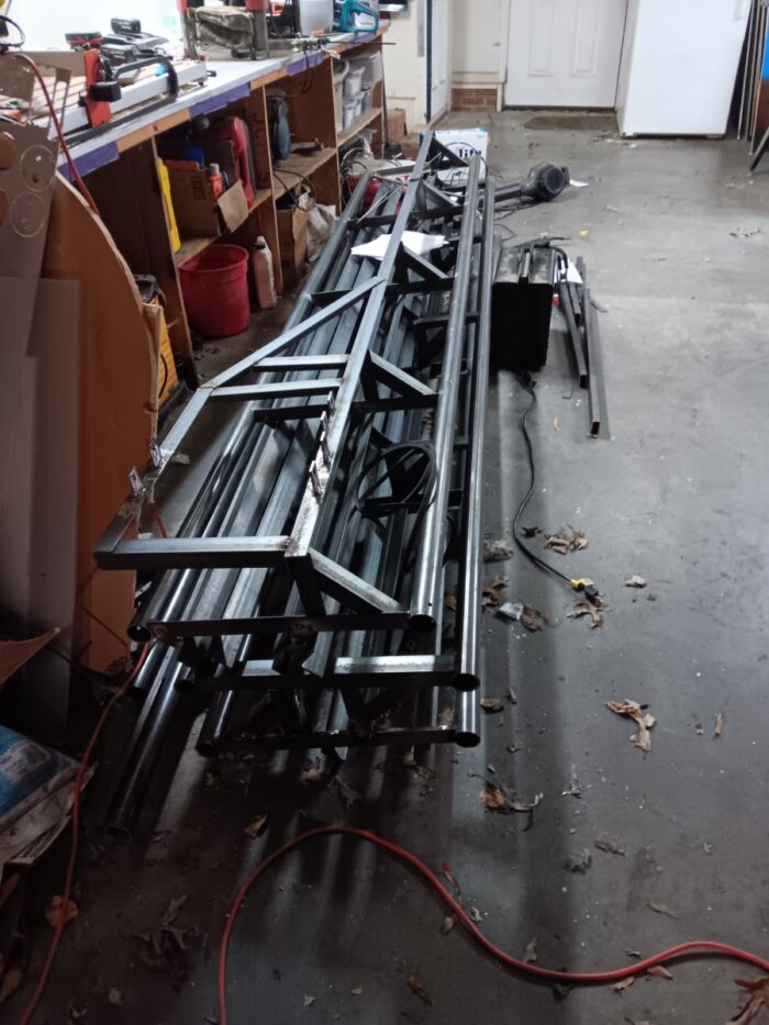
I get that you don’t believe I’m actually building the world’s BEST backyard coaster. Well, It’s not finished yet, but we are making progress. Here are some pictures to prove it.
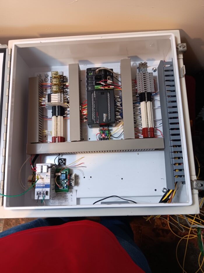
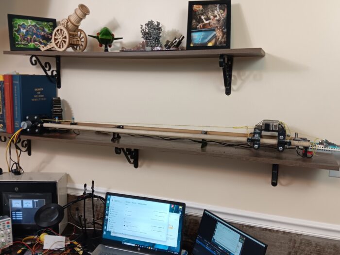
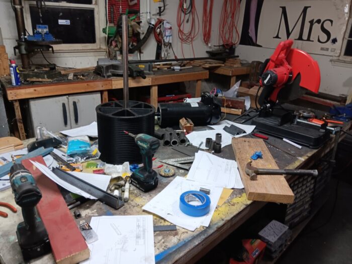
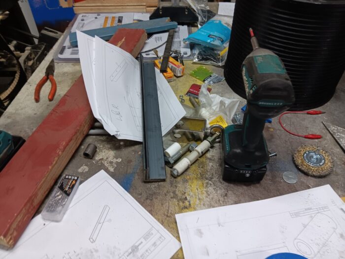
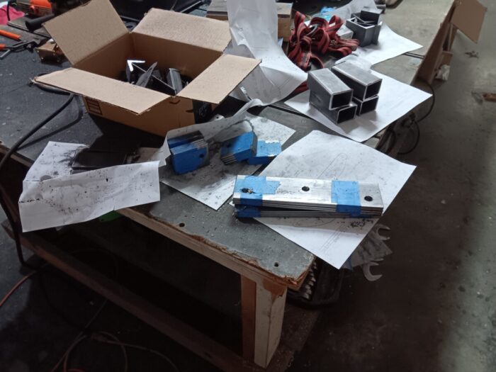
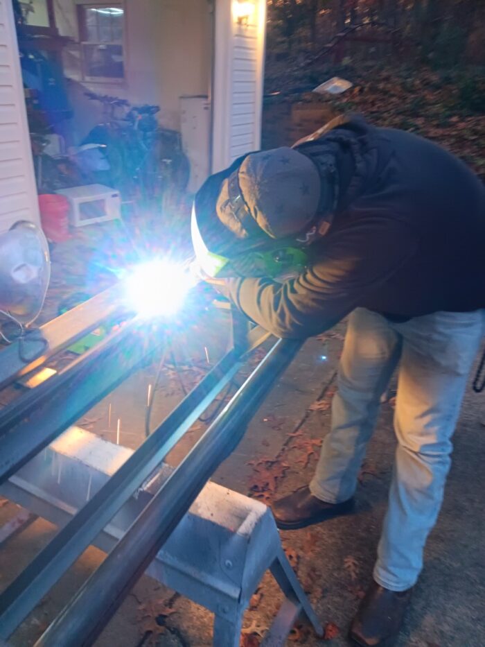
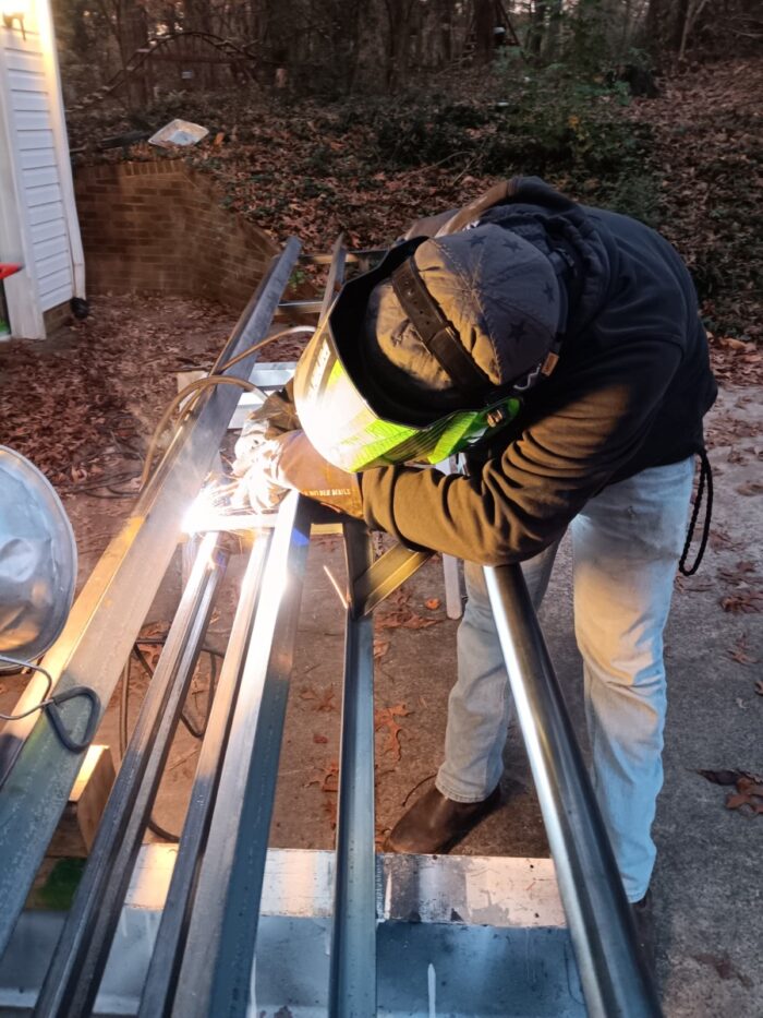
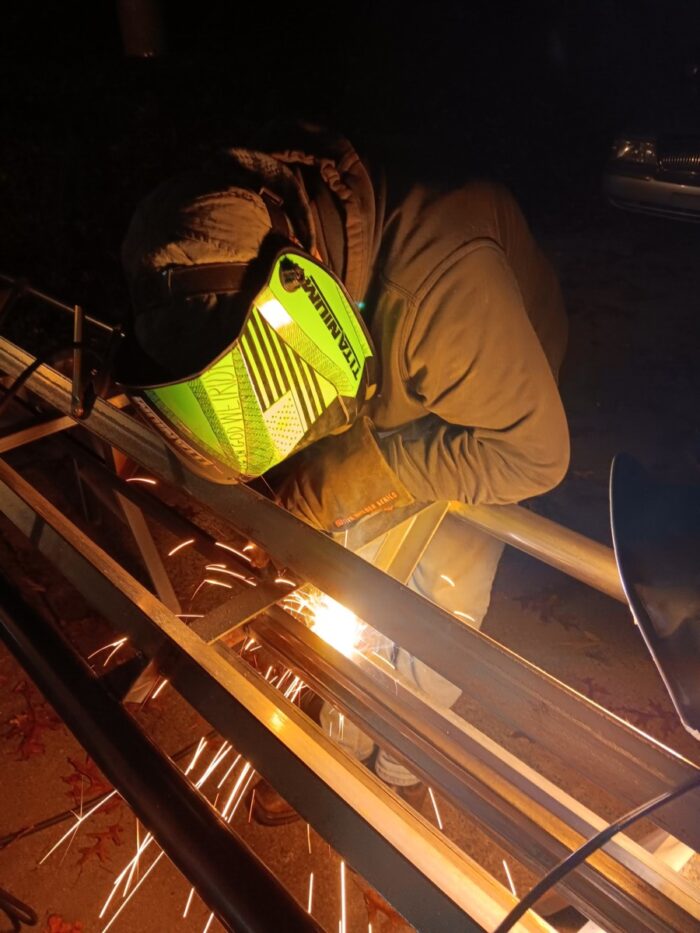
Kiddo’s pretending to have fun while paintingTwo launch sections ready for weldingSuper messy wiringWiring all betterWork station with test trackPiece part fabrication4 Launch sections ready for welding.
Exciting Cart Design Improvements for Our Backyard Coaster
A number of years ago, I heard that if you ever want to build your dream home; you will need to do it at least twice. Why, you learn things the first time and make adjustments. The same is true for this cart. Let’s take a look at the issues I was having and then determine how to fix them.
Track clearance (Top of cross tie to bottom of cart)
Bad seating
Short wheelbase
Wheel carriers weren’t the same
Wheel carrier secured with one cotter pin (single point failure)
Increase roll angle (better front universal joint)
Can’t cut square holes
Remove small bearings that prevent roll on the rear axle
Since this coaster will go upside down, we wanted to eliminate all single point failure locations like the cotter pin mentioned above. We also increased the size of all members to increase strength of the design. Result: better cart with increased safety and comfort.
Video – Capacitor Charging Issues – PLC Controls 4
In part 4 of our journey to the world’s Best Backyard Coaster, we encountered some issues with our capacitors. They are not charging evenly. So in order to get an accurate voltage rating of the bank, we will need to measure a peak voltage of 170 on a 0-10V scale. We also need to read voltages that have different ground potentials.
Using op amps and voltage dividers will help us solve these issues.
This one is member’s only so please join to support the channel.
Yes the last free video – sign up to see the rest of the series for creating Tilley’s Terror, our backyard roller coaster. We will discuss the launch system of our backyard coaster and how error codes and failure modes will play a part in our design. We never want it to fail, but when it does (and will), we want it to happen in a way that is overly safe and prevents injury to the rider and those around.
Coaster Launch Dog Motion on Test Bench with PID Controls
We are moving forward on our launch system for Tilley’s Terror. Our coaster launch, well at least the prototype, is taking shape as we are now able to move the launch dog on the track. Watch to see what obstacles we faced and our next steps.
hey welcome to the mentor engineer I’m excited to be here made some progress on my PLC control system as you can see from up here we have our card on there now you can see we got our tensioning device in the back there so it’ll always stay in the right spot and have tension on that cable which is very important special shout out to Austin who rejoined as a member I appreciate that and we are very thankful for everybody who is supporting us uh and if you aren’t please take a second to like share and subscribe and hit that join button help help support make this dream a reality so we had some issues before on our P control when we go to our PID Loop here we have our set point variable the dark blue line and then we have the actual point which is this lighter blue line the problem is is that the blue line when we launch changes very quickly and it was very noisy signal so we wanted to smooth that out you could see that here see how it’s launching and then all of a sudden we have this weird thing where the present value just jumps up and then the set point does as well and I have to figure out what is causing that because that is not good uh so I ended up finding that what is causing that is a inconsistent for formatting of my variable so it was just seeing a large jump so what would happen is the cart would eventually go on one side then go on the other side then go on the other side just keep going back and forth uh really slowly for you know forever I let it run for a couple minutes and it just like that so you can also see the noise here in this signal and that’s just not good so what was causing that was the noise is created by me reading in a bunch of points coming in using the plc’s CPU which might not always have the right clock time and it’s coming in very fast so seeing the difference between a high and low might get overlooked so you might read two or one or none instead of you know the proper number so how do we fix this well what we need to do is use another high speed counter to count the signals coming in from our profile so our profile is a trapezoidal profile so it’s going to look like this kind of ramp up have a steady state and then ramp back down and then be at a low rate all right now it’s outputting pulses which is 50% on 50% off however that’s not what I want so what I’m going to do is I’m going to count the number of pulses that come in and that’s going to make it look like this as it as it ramps up and you’ll see that in a second now I have my ramp in time a lot less than my ramp out because I want a little bit of ramp in and I want a large portion where the velocity is steady and then it’s going to fade back out and at that point when it starts fading back out the cart and the the launch dog are going to naturally separate luckily I had an old uh high-speed counter sitting around mainly because I blew out the outputs on it yes there is a difference between 5 amps and. 5 amps so when it calls for you know5 amp make sure you put A5 amp fuse in however the counters still work great cuz I didn’t blow those up so that will smooth smooth out that curve nicely and we’ll see how that follows our data just a second so what I’m going to implement now is a stage gate system so this prevents things from interacting with each other and allows the logic to be clearer for example when I first start my motion I’m going to start moving this way right now it’s only for two seconds but eventually it’s going to set go this way and hit all the proximity sensors and latch those on so I want to make sure that my high one and High two are active reading as a check and then it’s going to go all the way back and do that so that’s two stages stage one is moving this way till I hit both of the highs once I get both of those I’m going to go to stage two and move it all the way back so when I’m in one of those two stages I can’t be doing other things all right I can’t be moving forward and backwards at the same time I can’t be uh launching at the same time I’m going backwards we’re not doing that so it prevents things so I can look at very precise things and see where those things are going wrong and troubleshoot them then so when I look at my program here this is the initial stage uh it’s loading some stuff here it’s loading the high-speed counter this is loading the analog inputs and outputs uh here it is setting the the the EOP check so we’re always going to check that it’s going to check uh put our set point in there and at this point it’s going to jump to our initial homing so here we reached the EOP check we’re going to be looking at our two eops and here’s our second one on the panel put that on and at this point our EOP out would be okay but I bet I’m in program mode yep so that’s not going to work right now we’re then going to be looking at our proximity sensors and if any of these proximity sensors are high it’s going to latch those on because we’re going to be going past them very fast and they may not trigger automatically so we’re going to once you see a pulse hey latch that thing on until something else breaks that so here if we see our home proc is on if and are and we’re not launching it’s going to be uh latching this on and then that latch will will stay on forever uh until of course we are launching and then I’ll release that so here in the initial homing position I can press this button and it’s going to start doing things um it’s going to start this 2cond timer and it’s going to tell it to go this way and to Output a signal up here and then to latch it on so it’s going to go this way two seconds now eventually I’m going to have uh these two switches uh reset it so I have to hit these two switches uh and at that point it’s going to go and once that timer is high it will go to the next stage which will be to reverse Direction and force it back this way and it’ll run until it hits the end of the the proximity switch which is monitored in right here there we go and then it will go to the next stage which is stage 32 in stage 32 we’re going to move off that proc switch and we basically tell it to turn on your P ID and then at at that point it’s going to go ahead and uh start an 8sec timer it’s got 8 seconds to move there and eventually there’s going to be a proximity switch there that’ll verify that and then at that time it’ll be ready to launch when we’re ready to launch we enter stage 100 here uh we load up that trapezoidal profile I was talking about you write it into the memory and then we got a whole bunch of stuff here but here’s the launch button once that goes and our EOP is okay we’re going to start outputting data we’re also going to read in our high-speed counter right here and write that to the track set point and then once we have overtravel we are going to go ahead and uh set a 4C timer it’ll probably be more closer to six seconds uh in the real version and then it will uh activate a jump back to finding homes so as soon as it finishes launching it’ll wait a few seconds and then go back home all right so let’s see this actually work right all right so we’re going to go ahead here put it into run mode all right we got to put our panel e stop back onop and now we’ve got our EOP okay all right let’s scroll down we’re waiting to home right here let’s go ahead and hit the home button now it’s going to go this way two seconds now it’s going to reverse hit the and stop and now we’re in stage 32 and it’s coming off there and then after 8 seconds you just heard click it shut off so now we’re ready to launch so let’s go here to launch this is the launch stage so let’s go ahead hit the launch button it’s going to load the profile hopefully this will be successful and it’ll launch and we’re [Music] launching all right now it’s going to come back obviously it’s going to have to be a little bit faster than that right and it’s going to back off the proc switch and we’re ready to launch again all right now you can see here our data that blue line is a lot smoother than it was before so let’s go ahead and launch and we can see how closely our output monitors the input vice versa actually all right we overshot here and now we’re coming back you can see it Ste down here that’s just because the CPU is in manual mode so it’s not uh cycling as fast as it normally would that’s cycling about once a second or something where it’s upda you could see that the speed coming back was smooth so it wasn’t really an issue all right well that’s where we are next stages we’re going to get some proc switches up here we’re going to have one that makes sure that we got to the home position uh so that we know we’re in the right spot when we go ahead and put the launch dog up we also need two high side proc switches on this area so we’re going to be installing those we need to clean up the wiring in the box and then we need to add the those new proc switches to the ladder logic and interlock stuff and throw in some error warnings so that’s a lot of next steps that’ll be in the next video hey thank you for watching and have a great day please take a second to like share and subscribe adios scaps