As technology improves, mechanical designs have become sleaker and more compact. One exception has been electric motors. For decades, the shape and form factor of a motor has remained constant. Its consist of a large cylindrical body with a shaft protruding out one side.
If you are trying to accurately control motion in a joint, this can lead to a bulky situation. In many applications you are going to need: a motor; a gearbox to reduce the speed or change direction of motion; an encoder to map the position; bearings to support radial and thrust loads; and hoses or wires to be routed external to the whole apparatus. What A Mess!
Well, that has all changed; for the better! The Solution: Frameless Motors
A Frameless Motor separates the components of a traditional motor and removes the housing (frame) and bearings. The stator and bearings are built into the structure removing the need for duplicate structure and bearings. A low profile encoder can also be added. The rotor is inserted and can be designed with a hollow shaft allowing hoses and wires to pass.
How Does A Motor Work?
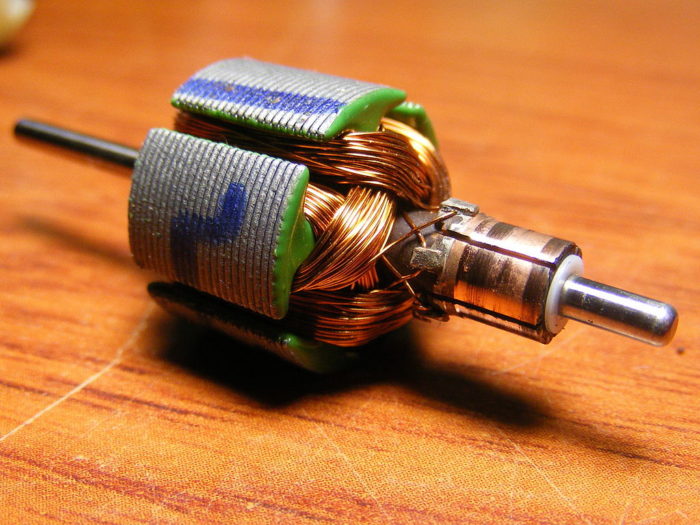
In a DC (direct current motor), there are electromagnets, minimum of 6, attached to a rotor (spinning part). The rotor is placed in a stator which has permanent magnets mounted on opposite sides.

Jjmontero9 / CC BY-SA (https://creativecommons.org/licenses/by-sa/3.0)
On the rotor there are contact pads (on right). These contact pads are connected to two electromagnets having opposite polarity. Brushes are used to transfer the electricity to the rotor on the contact pad, which energizes the electromagnets. As a result the magnets will want to attract and turn the shaft.
As the shaft spins, one set of brush contacts will drop off as another is being turned on. This ensures that a DC motor will always be able to give full torque.
Other Motor Types
DC motors aren’t they only type of motors out there, but they are the easiest to understand how they work. AC motors are speed controlled by the drive frequency which is 60 Hz in the USA and 50 Hz most other places. There are also stepper motors and synchronous motors.
All motors have the same two components, the stator and the rotor. The stator is the stationary outside component and the rotor will turn when electricity is applied.
Traditional Motor vs Frameless Motor Application
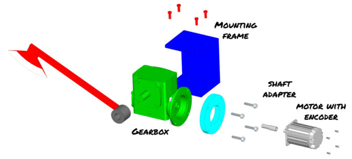
In a traditional style motor application you will have the components shown below. There is a lot of redundant structure and multiple bearings. Many times the motor shaft and gearbox shaft are not the same diameter and need a shaft adapter. In this case, we need the light blue spacer plate to compensate for the shaft adapter and to allow mounting to the motor. There is so much redundancy and we have little control over the components available.

The gearbox also mounts oddly because it has a hole pattern on top and bottom. This means that it must be sandwiched in between two plates. As someone who designs welded structures, this is difficult to do as the welding process will distort the gap. Once welded, there is little opportunity for adjustment if the gearbox is misaligned.
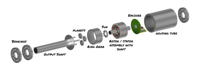
In a frameless motor application, this is all changed. The entire assembly mounts the round tube on the right. If this is part of a robotic arm, you can weld the tube to the end of the arm and then bore out the tube. This will account for any misalignment.
In the diagram below, you can also see that all of the components will fit in a much smaller envelope (and it looks cooler).

Custom Artwork By Stephen Schandel
We have reduced the number of bearings from 6 (4 in gearbox, 2 in motor) to 3. This will result in less friction and greater efficiency.
Benefits of a Frameless Motor
Just because something is different, doesn’t mean that is it always better. With frameless motors, there is a significant benefit in many applications.
The main benefits of frameless motors are increased efficiency and productivity, reduction of components like bearings, reduction of structure, smaller footprint, and improved hose and wire routing. All of these combined lead to lighter weight and decreased maintenance.
A better way of saying this is a frameless motor lets you have control! As the designer, you have complete control over every aspect of the design including the form, fit and function. No more adapting a design to the motor’s frame size.
Let’s explore this more closely
Increased Efficiency and Productivity
Gearbox
Going to a frameless motor usually means using a larger diameter motor. This can be very beneficial because a large diameter motor can produce more torque. Traditionally, if you needed more torque, you had to use a gearbox to increase torque and reduce speed.
Gearboxes have inefficiencies from the gears meshing which is wasted energy. Unless you get a precision gearbox, there is an issue of backlash or slop. Backlash is a measure of how much the input shaft can be reversed without any change on the output shaft. If you are looking for precision positioning, this can be difficult if not impossible.
With the larger motor diameter, there will be greater torque generated from the motor and you can completely eliminate the gearbox. No more slop and it will run quieter. Think about it, noise is just wasted sound energy.

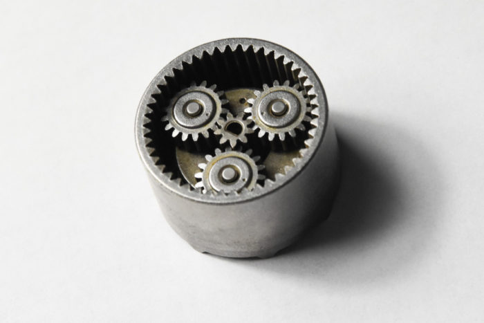
If you still need a gearbox to get the torque you need, consider incorporating a planetary gearbox into your design. The sun, in this 2 stage gearbox in this is a 36:1 system shown above, can easily fit onto a motor shaft and then be pressed into the housing. This can be done with the addition of only one bearing on the output shaft.
Bearings
Bearings are also a source of inefficiency. Each bearing creates resistance to motion and a traditional setup has lots of them. Think about it: there are 2 in the motor, 2 to 4 in the gearbox, and 2 more on the output shaft. Two more if you need an encoder. That’s a lot of bearings!

In a frameless design, we can remove the gearbox due to the increased diameter. We can also incorporate the motor bearings into the output shaft bearings reducing it by two more. The brains of an encoder are relatively small and there is no need for it to have any bearings.
We have now reduced our assembly from 10 bearings to 2. Yea!
Reduction of Components
All these components that we have eliminated contribute directly to increased productivity. First of all, we have eliminated the hassle of purchasing, managing, and storing multiple parts. This is a hidden cost in any design.
If we don’t have to buy these parts, we also don’t have to assemble them. Now we can produce more product in the same time.
Finally, when there are less components, there is less that can go wrong. This leads to the product having longer up times and reduced time troubleshooting when something does.
Reducing components directly leads to increased productivity and a more durable machine.
Faster Motion
Another way that production is improved is with movement. When using a gearbox, you may be limited in your input speed. If you have a very high ratio gearbox and you might have a slow output speed which means slow travel from one position to another.
If a gearbox can be removed, this will lead to faster settle times. This is the time it takes for the motor to hone in on the final position. I once had an apparatus where a motor drove a chain that controlled linear position. When it got close it would slow down, but as it did, it became jumpy.
By jumpy, I mean that it would move 1/8″ (3mm) and then stop for a second before jumping again. It was very difficult to position it closer than 3/16″ (5mm). The settle time on this was very lengthy (over 15 seconds) because the chain would oscillate on each side of the target multiple times. We ended up switching to a precision gearbox and increasing tension on the chain. This removed most of the backlash and we were able to get the settle time down to 2 seconds.
Reduction of Structure
If we buy the gearbox, motor and encoder separately, we are going to have housings for each of them. This is wasted material and money.
In a robotics application, this can be a lot more mass that needs to be repositioned. Since Force is mass x acceleration, we are going to need more force to move this. With more force comes larger structures, more weight and more energy to move it.
By combining the motor, encoder and gearbox into one structure, we minimize weight and footprint. This leads to less power needed and greater system efficiency.
Improved Hose / Wire Routing
I can’t say how difficult it is to route hoses and wires external to moving joints. As the joint moves, the wires will tighten and loosen. Too tight and they might snap or kink. Too loose they might catch on something. It is a delicate balance.
I did work on one aerial lift where the hoses were routed through a hollow shaft. This was a godsend because the unit was designed to work around trees and the hoses were well protected from getting snagged. As the joint changed position, the hoses rotated on the center-line, but never changed length.

Servotecnica, CC BY-SA 4.0 https://creativecommons.org/licenses/by-sa/4.0, via Wikimedia Commons
The same can be true in a frameless motor. You can choose a shaft that is hollow and run wires and hoses through it. This protects the wires and prevents them from changing length. If your application is for non-continuous rotation, you can simply run the wire and hoses in the hollow shaft. However, if you need continuous rotation, you still have the opportunity to add a slip ring or rotary joint to the design. The hollow shaft is magic!
Decreased Maintenance
Improved OEE by increased machine life and reduced maintenance. Similar to the above point, each additional component in a system adds complexity and the need for maintenance. Since frameless motors use comparatively fewer components, they also require much less maintenance than traditional motors.
Summary
From increased productivity, reduced structure, size and components; frameless motors are here to stay! I can’t say enough how much having the ability to run wires in a hollow shaft is a major benefit.
The one main drawback is cost. Some of these components like the shaft and housing are going to be custom. This leads to parts needing to be machined.
Every situation is different and needs to be evaluated. Even in small quantities or one-offs, using a frameless motor with a lot of machining will still make sense when factors like size are important.

