

When designing a piece of equipment, stability can be a significant issue. For stationary equipment, often securing the apparatus to the floor will ensure stability. However on a mobile piece of equipment, like a forklift or a crane, stability must be carefully considered along with its structural design.
There are four basic steps to determining stability: calculating the overturning moment, determining the stability envelope, calculating the stability moment and applying a margin. These steps can be applied to any object that has a risk for tipping over.
When considering stability, let’s define a few terms. First, what is the “stability envelope?” When looking at the unit from a top view, the stability envelope would be the outline of all the contact points with the ground. Be cautious, not all points are equal! For outriggers with a fixed foot, the furthest point away can be used. If there is a swivel foot, use the centerline of the pivot pin or spherical bearing. If tires are used, go to the center of the tire. In the case of a dually tire, go to the center of the dually. If a vehicle has a steering axle, do not use the tires. The suspension is very flimsy and a distance of only 12- 20 inches can be used without modifications.
Second, what is the “overturning moment?” The overturning moment is the sum of the moments containing everything on the unit that is directly connected to the load. In the example of a forklift, the overturning moment would include the weight of the mast as well as the lifted load.
Stability moment is the moment that resists the overturning moment. The difference between the stability moment and the overturning moment and is expressed as a percentage when compared to the stability moment
Everything that is not part of the overturning moment is part of the stability. Again with the forklift example, the stability moment would consist of the weight of the vehicle, the operator and fuel.
The final term is stability margin. This is usually measured in the extra capacity that can be lifted before instability occurs. These terms are related by the following equation.

1 – Calculate the Maximum Overturning Moment
The game for stability is simple; the stability moment must equal or be greater than the overturning moment for the product to be stable. It can be very easy if you know the loads and have a very rigid structure. Unfortunately, most situations are not this easy and more analysis is needed. There are several important things to consider when determining stability.
Loads – In most cases, the load is either a person or material and the force vector is pointed down. There are many times that the load is pulling to the side like if a man was up in an scissor lift and pulled sideways. A third cause of overturning moments is a rotating imbalance.
Unless guided by a standard, these side loads can be difficult to determine. Acceleration and deceleration are also loads that need to be considered.
Slope – Slope is a detriment in two ways. First, it can minimize the stability envelope which decreases the stability. Second, in most cases slope will increase the overturning moment by extending the distance the load is from the normal position
To calculate the overturning moment if it is on level ground. This will be usually be the cross product of weight of the components and the horizontal distance to where the load mounts. However, with side load and rotating imbalance, the force in question is usually sideways and needs to be evaluated by height.
2 – Determine the Stability Envelope
The easiest way to determine the stability envelope is visually. We will demonstrate that with an example of a forklift. The stability envelope is drawn between the centers of the three tires. This is a good assumption because forklifts are very rigid usually without suspension and rarely have inflatable tires. The location of the stability moment has already been calculated and plotted on the chart.

Rigidity – Rigidity (or lack thereof) acts in the same way that slope does. If the structure is flimsy, deflection can create an artificial or internal slope that increases the overturning moment. Be cautious if your structure flexes too much. This may cause problems with excessive roll or increasing moment arms
How to determine the location of supports:
- Solid tires – As mentioned above, solid tires can be assumed act at the center of the tire.
- Pneumatic tires – We can also assume the center of the tire, but as the tire looses inflation, the tipping point needs to be moved it.
- Dullie tires – (four tires on one axle) The safe assumption here is to use the center between the tires for the tipping point. These are pneumatic tires so deflation can cause significant impact to stability.
- Pivoting foot outriggers – This type of outrigger cannot build up moment at the foot so we need to put the tipping point at the center of the pivot.
- Non-pivoting outriggers – These outriggers have a fixed foot and can move the tipping point all the way to the end to the furthest reach of the foot. Often, the outrigger foot is slanted so that the furthest edge is the lowest part of the outrigger. There are two reasons for this. First, this accounts for any deflection in the outrigger. Seconds, that even on flat ground, the outrigger will contact the furthest distance providing maximum stability.
3 – Calculate the stability moment
This is usually the least complicated step. We will just calculate the weight and center of gravity for all the involved components that are not part of the overturning load.
4 – Factor in any margins required
Once the Stability Moment and Overturning moment are known, calculating the stability margin is simple. To do that, use the formula below.
At this point, you would want to compare this to any internal or external standards your machine needs to adhere to.
Forklift Example
Forklifts are a great example of stability. They are in use everywhere and there is a large impetus on the operator to make sure that loads are within acceptable ranges and operations on slopes are minimized.
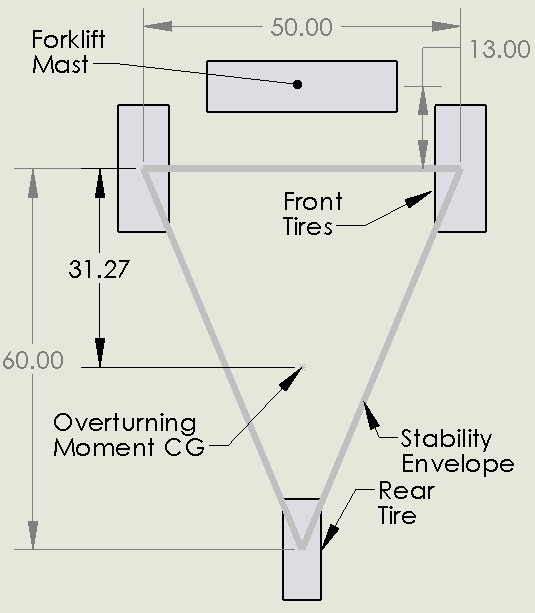
In our example, we have a typical three wheeled forklift. We will assume the forklift (including mast), rider and fuel weighs 3000 lb and the center of gravity is 31.27″. Our mast is pivoted 13″ in front of the front tires. The load weighs 2000 lb and the center of gravity is 20 inches from the mast. We will first perform this analysis on flat ground.
Stability on Flat Ground
We can first to determine the overturning moment if it is on level ground. This will be equal to 2000 lb * (13in+20in) = 66,000 in-lb. Next, the stability moment is 3000 lb * 31.27 in = 93,810 in-lb. You can see that the unit is stable by a significant margin by 29.6%
Stability on 5° Slope
Now let’s see what happens when the operator drives down a 5° with the load 10 ft in the air. This makes the analysis more difficult. The overturning moment changes because the load is shifted out front. Mo = 2000 lb * (13 in +20 in +120 in sin (5°)) = 86,917 in-lb. This example still shows that the forklift is stable, but by a much narrower margin of 7.3%. Adding 160 lb to the load would make it unstable.
A More Visual Approach
This method of calculation works well when there is a clear tipping line (like the front tires). It is a little more complicated when the tipping line isn’t easy to spot or calculate. We see this happen when the forklift starts tilting side to side. We don’t necessarily know from inspection if it will tip over the side or front. For that we will use a second method that is more visible.
The method below uses a graphic method to see the stability margin. There are three plots shown. The gray plot simply shows the stability envelope. The blue plot shows where the CG of the load will be as the forklift is setup on 5° slopes in all directions. The orange plot shows the combined CG of the blue plot with the unit CG. You will notice that the area relocates and gets smaller. From here, finding stability is easy. Just check to make sure the orange plot falls entirely inside the gray stability envelope.

How to improve stability:
Add weight to the unit: Adding weight will help, but slowly. In cases where a load is suspended far from the nearest support, adding 6 -10 lb of weight might only allow for 1 lb additional load.
Add outriggers: This increases the stability envelope. This obviously will not work when the equipment carries the weight while in motion.
Check for proper tire inflation – A low tire can significantly reduce the stability envelope or allow for more roll. Inflate the tires and retest.
Design a rigid structure and suspension – Intend for the entire unit to flip at all at once when instability occurs. This minimizes roll and the potential for more overturning moment to be generated.
Bolster the suspension – Making improvements to the suspension can drastically improve machine performance. The more rigid things can be the better.
- Adding suspension bump stops to axles prevents the suspension from collapsing making it more rigid. On a chassis front axle, it will allow the width of the front axle to be increased to the frame rail width. This will inversely affect the comfort of the ride.
- Adding torsion bars will cause the opposite side wheel to pick up sooner and increase the stability moment. Torsion bars usually have a minimal effect on the ride.
- Axle locks are a third option here. This is a device that will physically latch and unlatch the axle to the frame. The latch is intended to engage only when it is needed. This provides a smooth ride, but rigid structure when working.
Conclusions
Thinking about stability in a graphical way can greatly simplify the calculations and remove some of the mystery. It will also help determine if there are regions of instability that are not obvious. Using the analysis tools mentioned, and the tips to increase stability should give you the tools to make sound decisions and make your design more stable.