

The Problem:
There have been several times in my engineering career that I have needed to limit the force a mechanism can produce, but still allow for unpredictable amounts of deflection. This is very useful in cyclical testing when the test piece needs to have a certain load applied to it over and over. Usually in situations like this, you want to be able to setup a test machine and let it run continuously without the need for babysitting it.
Generally speaking for an application like this, using a rotating motor with a cam makes the most sense. The cam would then be attached to the test piece as shown. However, I can only produce the correct force when the test piece, link, motor and cam are all perfectly spaced when the cam is at its apex. Even if I could get this right, the nature of machines is that they wear.
If my test component needs 100 lbs. applied repeatedly, I could set that, but by cycle 1000, I could have worn multiple parts and lost most if not all my initial force. The cause of this is simply increased distance or deflection. At this point, you could design a complex control system to monitor the force and make adjustments to the spacing or the cam offset, but that sounds like a lot of work and money to me. I’m just not interested in that and you shouldn’t be either.
So here’s the solution:
We need to have a way to insert some flexibility into the system. The obvious place is to look at the link. The solution is to replace a fixed link with a rod and tube connected by springs. Yes, springs are the key to all this. So we may remember that a spring follows the formula F = k * x. Where F is force, something we are interested in, k is the spring constant and x is the deflection.
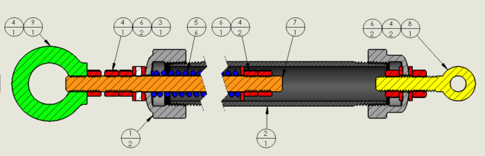
The mechanism shown below consists of several parts: the outer shell, the springs, the rod and some hardware. It is a pretty simple mechanism, but the most important and difficult part is selecting the springs.
What kind of springs do I use?
This is a great question. So this device will be used in tension, so we will need to use compression springs or perhaps Bellville washers. If springs are chosen, be sure to select closed and ground so that they can stack easily. To select the right spring, we must first decide what our load range is. Generally this should be about +/- 5%, but we can bias this. In our example of a nominal 100 lb, are we ok with 95 lb. to 105 lb.? We could also bias this to be 100 lb. to 110 lb.
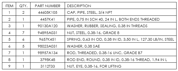
For this case, we will have the maximum load at 110 lb. We should definitely select the maximum loading of our spring to be at least 10% more than our capacity. We also want to look for a relatively low spring rate. In this case I looked at McMaster Carr and selected 9657K451. This is a spring with 124 lb. max load, a spring rate of 127.3 lb. /in, a free length of 3.50 in and a compressed length of 2.49 in. This spring should do fine.
How do I plan for deflection?
To estimate the deflection, be sure to consider all the components involved because they will all add up together. If we estimate this at a quarter inch, I would plan to double that in our calculations. With this apparatus, it is much easier to minimize deflection than to add.
In this case we will use half an inch as our delta, Δ. So let us look at what kind of deflection we anticipate. Using the spring equation, we will solve for x using the differential force required.
110 (lb.) -100 (lb.) = 127.3 (lb. / in) * x (in); x = 0.078 in
As you can see, there is very little deflection. What we need to do now is put multiple springs in series so that the deflections add up, but the force remains the same. We can now calculate the number of springs needed.
Δ = 0.50 in = n * 0.078 in; n=6.4
So we will need seven springs in series to give us the characteristics we want.
Designing the Housing
We are ready to start designing the rest of the machine. From our spring catalogue, we see that the outside diameter is 0.625 in and the inside diameter is 0.385 in. For the rod, threaded rod is the best choice. It is easily available in a variety of sizes and grades. This will be the piece that we set our target force with so we want the infinite adjustment it gives. The logical choice here is using 3/8-16 threaded rod because it is 0.010” smaller and provides a great pilot for the springs. The pilot is important because it ensures that the springs stay stacked properly.
The outside housing is a little more difficult.
We have to be strong enough to carry the load, be able to assemble it and most important, we don’t want to have to machine a bunch of parts. The best solution I’ve found is using threaded pipe with pipe end caps. It allows for items to be assembled and requires no additional bolting or machining.
In our case, a ¾ schedule 40 pipe will work well because it has an ID of 0.824 in. Since we are using seven 3.5” long springs (24.5”) pieces, we need to have at least that length of housing, or do we? Ok, so we can cheat that a little in this and many other cases. In this case, I would choose a 2 foot length of pipe since it is commonly available in most hardware stores.
A little fabrication
So we now need to drill a hole in the end of each end cap, I recommend doing this on a lathe to keep the centers aligned, but in a pinch, doing it by hand will work. Just make sure you mark the center well and punch it first. The hole should be sized slightly larger than the threaded rod.
Assembly and calibration
From the drawing you can see that a few nuts, washers and eyebolts complete this assembly. If eyebolts don’t fit your application, you may need to do a little more engineering work. Once assembled, you can calibrate by hanging the housing from the crane or other structure.
Apply a known weight, in our case 100 lb., to the end of the threaded rod. The rod will extend until equilibrium is reached. Adjust the two nuts on the rod until it is snug with the housing. Jam the nuts together to ensure they don’t move. You can then add another 10 lb. to the existing weight and see how much the nuts extend. It should be just less than the ½” we planned on.
If you would like to build this version of a force limiter, this is the bill of materials to do so. All of these parts are available at McMaster-Carr.
A few final thoughts.
I mentioned using Belleville washers instead of springs. While Bellville washers will work, you can really only use them with very small deflections. A good candidate for this application has a deflection of about 0.008 in at rated load. This would require around 600 washers to get the ½ in of deflection that we needed. It would also cost and weigh much more and have a longer length. It is recommended that Bellville washers only be used with deflections that are less than 1/16 of an inch or less.
It is recommended to use a rubber washer in between two larger washers on the threaded rod. When the link is unloaded, it will make a loud thud otherwise. I realized this on the first one I built when we needed to run a test that lasted several hours and it annoyed my fellow coworkers (not to mention the headache I got).
Finally, I recommend using this in only tension applications. You can use it in compressive applications but you need to worry about buckling and eccentric loading. This is a headache due to all the calculations and tolerances you will need to consider. You just don’t want to go down that road.
If your application needs to be in compression, I recommend getting a cylinder and maintaining constant pressure on the extend port. The other benefit is that if you use a cylinder, you can also make a simple controller for it to cycle the load as well.
Conclusion
In conclusion, a force limiting device like this is easy to design, assemble and fabricate. It can make life much easier in situations where you need to apply controlled loads repeatedly. You can also impress your friends with your smarts at the same time.