

Many times in my career, I have found the need to determine a cylinder’s characteristics from an assembled machine. This is often the case when scoping out the competition. Most critical dimensions can be found with a tape measure in a matter of minutes. The cylinder bore cannot.
Determining the bore or inside diameter of a hydraulic cylinder without disassembly is possible by measuring the barrel outside diameter. The wall thickness can be estimated using Barlow’s formula Finally, the bore can be calculated and then compared to common cylinder bore sizes.
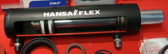
So measuring the rod diameter, retracted and extended length of a cylinder is easy. It is far harder to take the cylinder apart and measure the ID. (It is by far very messy as well and you could damage the cylinder). Even with the giant cutout in this cylinder, getting an accurate measurement is tough.
Furthermore, it is quite unnecessary as well. Keep you hands clean and simply measure the barrel outside diameter.
Determining System Pressure
Knowing the system pressure is a critical first step to determining the bore ID. Most hydraulic systems operate in the 2400 psi to 3000 psi (165 to 207 bar) range.
We can look at the hydraulic hoses for pressure ratings on the inlay, but that can be misleading. A hose that is rated for 4500 psi (310 bar) can be used on a 2400 psi system with no issues. You may have better luck with this method if your cylinder uses thermoplastic hoses.
If the machine doesn’t have a pressure gauge already mounted on it, get one and install it. Often there is a location where a quick connect fitting is ready for a gauge. I recommend using one that goes to 5000 psi in case the pressure is higher than the expected location.
Once the gauge is installed, power one function so that a cylinder is either fully extended or fully retracted. This will cause pressure to go over relief and our gauge will indicate the maximum system pressure. Make sure that the function selected won’t damage the machine and it doesn’t have any pressure reducing or limiting valves on it.
Measuring the Barrel
Accurately measuring the barrel can actually be a little challenging. On an assembled machine, there my not be adequate access to the cylinder where the aren’t ports, feeder tubes, or welds. Perspective also makes it difficult to get an accurate reading of the barrel diameter. With these two issues, using a tape measure to determine the barrel size may be out of the question.
Measure the Circumference Instead
Measuring the circumference is often a better way to measure the barrel diameter. You only need limited access and you can line up the numbers easier. If you have a ‘pi’ tape measure (reads diameters when wrapped around circumference), use it. Otherwise use a standard tape measure.
I recommend using a 1/2″ (13mm) wide or less tape measure so that the arc across the tape measure lays flat and doesn’t interfere much with the measurement.
If you only have a 1″ (25 mm) wide tape measure, I would suggest turning the tape measure over so that the numbers are on the inside. This way the tape measure lays flat against the barrel much better.
For either type of tape measure, I also burn the first 10 inches of the tape. By not using the first 10″ of the tape, you prevent the end clasp from interfering with the measurement. You could use as little as 1″, but I often forget to subtract that from my measurement afterward. Ten inches is a little more obvious that something is wrong.
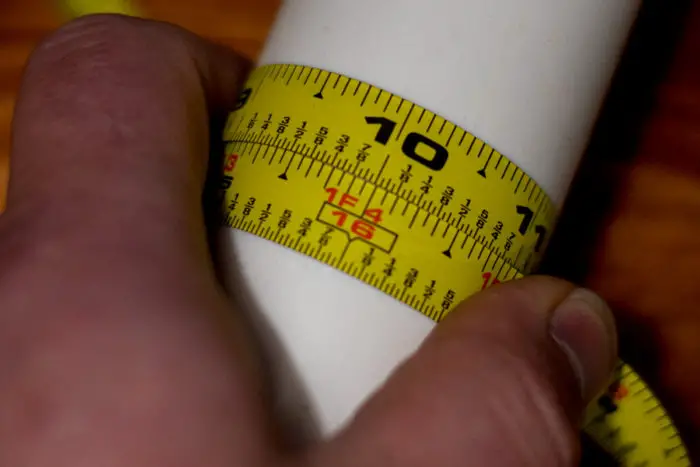
When measuring, line up the tape measure as shown and read the value where it lines up with 10″. Then subtract 10″ and divide by Pi to get the circumference.
Determining Wall Thickness
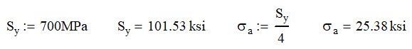
A key element of determining the wall thickness is determining the tube’s material strength. Most tubing used in cylinder manufacturing is high strength tubing that has a tensile strength of 101.5 ksi (700 MPa).
Yes, some manufacturers use even higher grade steels, but this is rarer than we think. When considering cost and strength, it is a good assumption to use this material.
Design Factor
Since cylinders are often used in overhead lifting or lifting of human life, they are designed to a 3:1 design factor at minimum on burst strength.
Some design standards require a 4:1 design factor on burst pressure. There are many reasons for this high design factor:
- Loss of life if failure
- Temperature increases (makes oil less dense and increases pressure)
- Cylinder may be loaded to higher pressure than system pressure
- Induced loads
- Shock loads
- Axial loadings
Ultimately we don’t want the cylinder to fail if the pressure increases by a significant amount. So we use a 4:1 design factor.
Barlow’s Formula
Barlow’s equation is a simple formula that measures the circumferential or “hoop” stress of a pressure vessel. This equation accounts for the pressure, average diameter and wall thickness.
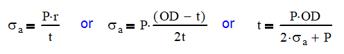
There are differing opinions on whether the OD, ID or midplane of the tube should be used for this equation. Most use the mid-plane diameter so we will use that here. It is shown as (OD – t) in the middle equation.
The second equation (right) is the same only rearranged to give us the thickness, t, without using an equation solver.
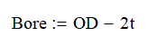
Once we have the thickness, we can find the bore by the following equation.
Pulling It All Together
Now once we have the bore diameter, we have to make some judgement calls. This calculation is theoretical and you will come up with a very specific answer. It won’t be the actual diameter of the bore, but it will be close.
Minimum Thickness
Cylinder manufacturers will generally limit the minimum thickness to around 3/16″ or 5 mm. This prevents dents and dings on the surface from causing issues with the seals. It also limits thermal issues, addresses axial and buckling loads. It is also easier to handle and store.
Common Bore Sizes
Cylinder bores come in standard sizes which mean that they are somewhat predictable. They are 1.5, 2.00, 2.50, 3.00, 3.50, 4.00, 5.00, 6.00, 7.00, and 8.00. Greater than 8″ cylinders usually step up in 2″ increments.
These are not the only cylinders bore sizes available. I have seen and used a 4.25″ and 4.50″ cylinder.
Two Quick Examples
If I measure a cylinder that is 4.50″ and another that is 2.94″, what are the bore diameters? Both cylinders see system pressure of 3000 psi.
Let’s start with the 4.50″ cylinder.
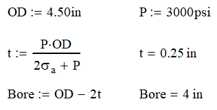
You can see here, that the bore calculated is exactly 4.00 in, that rarely happens. We can conclude that the bore is 4.00 in. If the diameter was a little larger or smaller, we could make the same assumption.
Now, the 2.94″ cylinder.
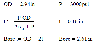
Our bore is calculated to be 2.61 in. We can see that the thickness is 0.16 inches which is smaller than the minimum thickness. When we increase the tube wall thickness, we get very close to a 2.50 inch bore diameter. We will use that.
Conculsion
With a simple measurement and few quick calculations, we can determine the bore diameter of a cylinder without ever looking inside. Knowing the tensile strength and the system pressure can get us close enough to accurately determine how powerful a system we have without disassembling the cylinder.