

In the many gear systems I have designed, I am faced with the question of which diametral pitch is the best. Keep in mind, there is no absolute right answer here, but nonetheless I will share the guidelines that have helped me over the years.
Selecting the right diametral pitch for a gear comes down to two things: selecting teeth strong enough to transmit the torque and using long ‘line of contact’ or ‘line of action’ that is above 2.2.
Unfortunately, we do need to take a little aside to specify some terms here. I promise, it will be brief.

Lands – They are the “flattened” section of the tooth. The top land is the land at the maximum extent of the gear and the bottom land is at the minimum diameter. When meshed, there should be a small gap between the lands.
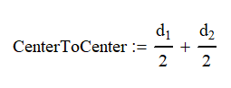
Pitch Circle – The pitch circle is the effective diameter of the gear. Ideally you will want the pitch circles of two gears to be tangent to have the correct distance between them for meshing. This information is usually given by the manufacturer and is commonly referred to as the variable “d”.
Diametral Pitch – Diametralal pitch is represented by PD and has units of teeth/in (TPI). It is the number of teeth on the gear divided by the pitch circle (d) of the tooth. This information is supplied by the manufacturer.
The diametralal pitch must be the same for gears to mesh.

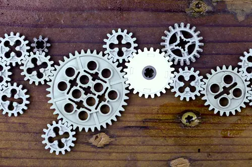
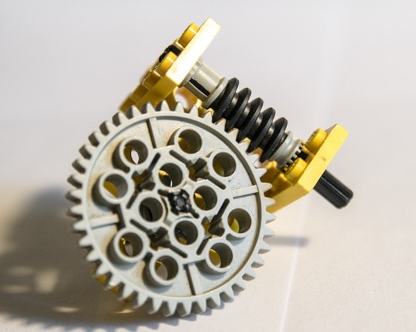
Since I like Legos, we will use them to do a little example. Lego block have the holes 0.314” (8mm) apart so we will use that as our measurement. If I mesh two of the 8 tooth gears, we can see that the pitch diameter is one hole or 0.314 (8mm). Our PD is 25.5 TPI (1 tooth / mm). The 16-tooth gear uses 2 holes or 0.628” and Our PD is 16 / 0.628 or 25.5 TPI. We would also find that the 24 and 40 tooth have a 25.5 TPI if we did the math. These gears mesh together because they have the same pressure angle and diametral pitch.
Calculating Tooth Forces on Gears
Spur Gears
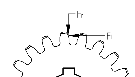
Calculating the forces on an involute spur gear is easy. Because of the involute tooth design, the worst loading cast is when the gears mesh where the pitch diameters intersect at the tangent point.
Since the gears mesh at the pressure angle (14.5°, 20° or 25°). we will have two components to deal with. The tangential force and the radial force.
The tangential force, Ft is the input force component that transmits motion. Because of the gear’s pressure angle, we now have a radial force, Fr, that pushes the gears apart. As you can see, having a higher pressure angle will create higher radial forces.
To maximize efficiency, ball or roller bearings are often used even when rotation speeds may be slow enough to use cylindrical or other non-moving bearings.
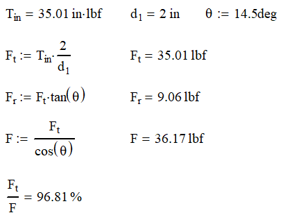
We usually know the tangential force from the torque applied to the gear set. By solving for the statics, we can find Fr and the total force F.
The total force is almost a useless number, but it does give some indication of how efficient the system is. The higher the ratio of Ft/F is, the more efficient the teeth are.
Continuing our example, we find that the forces on the gears are as follows:
Helical Gear Forces
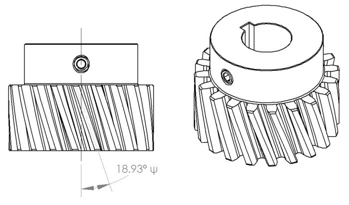
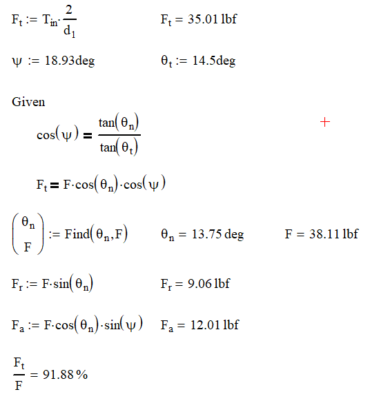
Helical gears have an added level of complexity not only in design, but also calculation. In the gear above we still have a 14.5° pressure angle, but the teeth are cut at a 18.93° angle from the shaft axis, represented by ψ. From the diagram below, we slice the gear two ways with θt equal to the gears pressure angle and θn which the pressure angle when viewed from the end of the gear. Now we can start calculating our gear forces.

Since the gear tooth is cut at an angle to the rotation axis, it should be no surprise that we are now going to have an axial component in our calculation. As a result, you will need to think of how you want to deal with this load. Having a set screw taking this load might be acceptable if you are using small torques, but you will probably need to upgrade to tapered roller bearings or thrust washers if your loads are high. Obviously, having the axial component will decrease our overall efficiency of the system as our ratio of tangential force to total force dropped from 97% to 92%. One thing to note about changing from our spur gear is that the radial force remains the same.
Tooth Stresses
So, it all comes down to the force and stress exerted on the tooth. For as complicated as the gear tooth profile is and all the points that the gear can contact at is the formula is surprisingly simple. This is where those really smart guys that came up with the involute profile really earned their money.
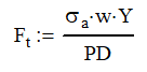
Where Ft is the tangential force, σa is the allowable stress, w is the effective width of the gear, Y is the Lewis form factor and PD is the diametral pitch. As always, watch your units.
You can see that as the pitch diameter is increased, the maximum tangential force allowed will decrease. This makes since as the profile for each tooth will decrease in size.
If you don’t have enough tooth strength, you will need to decrease your pitch diameter.
Lewis Form Factor
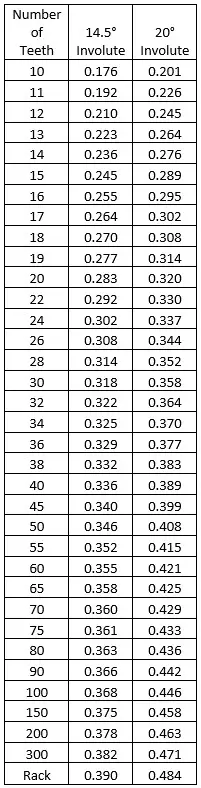
The Lewis Form Factor is the real genius of the operation. This factor takes in all the geometric variances with the involute profile and puts them in a neat little table shown here. You can see that increasing the number of teeth increases the factor as well as going to a higher pressure angle.

If you want to increase your tooth capability, you can increase your allowable stress, gear width, or use larger or higher pressure angle gears. You can also decrease the diametral pitch, because fewer teeth per inch means larger (and stronger) teeth.
Barth Speed Factor
The equation for finding the allowable stress is for static gear meshing or those running at very low speeds. Unfortunately, we probably want our gear systems to run at higher speeds so we need to add in a factor to account for speed.
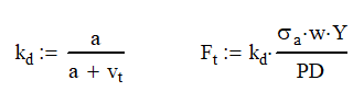
Adding the Barth Speed Factor, kd, decreases the allowable tangential force. The gear speed is the velocity of the teeth at the pitch diameter measured in ft/min. The constant a is based on the gear design and is 600 ft/min for regular gears and 1200 ft/min for precision gears.
With these equations, you should almost be able to calculate the tangential force. We are only missing what the allowable stress is. Unfortunately, I cannot give an easy answer. I can only give the lawyer answer: It depends. Here are some of the factors that will play a role in calculating the allowable stress
- Hertzian contact stress
- Gear ratio
- Material
- Surface roughness
- Lubrication
- Overload
- Dynamic Load
- Temperature
Each of these factors can be very hard to determine. I wish I could be of more help, but every case is different. My advice to you is this, go conservative! Calculate the maximum load that system can see and use a design factor or 3:1 on yield stress.
Make sure that your gears are well lubricated as well. Designing to these criteria will put you on the side of caution. Remember nobody complains if your gear system lasts forever.
Line of Contact
The Lewis Form Factor only takes into account a single tooth meshing at a time. However, this isn’t the case in real life.
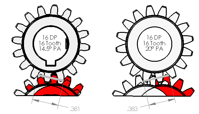
As you can see from the image above, the gears start and end meshing along the line. This line will always be perpendicular to the involute profile where it crosses the pitch circle. The length of the line in important because it let’s you know the gears are going to mesh.
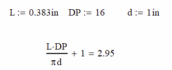
Using the equations above, we see that at any given point in the meshing process that 2.95 teeth are meshing. This number should always be above a 2.0 for good meshing and ideally no lower than 2.2. If the number is too low, you run the risk of slipping teeth when you drive the system.
If the number is higher than 3, you can use this as to distribute the load to more teeth and increase the total torque transmitted.
Before you go hog wild on this, keep in mind that the precision and material of the gears make a difference. The teeth on plastic gears will deflect more than on steel gears and will distribute the load better. Also, if your gears aren’t machined well, there may be teeth that don’t touch at all.
You can increase the line of contact by increasing the diameter of the gears. When you do this, you also reduce the tangential force on the gears as well.
I’m sure there is a way to calculate the length of the line of contact, but I have found it simpler to model the gears in both positions using 3D CAD. Many suppliers allow you to download models of their gears as long as you don’t fabricate your own gears from their model.
Conclusion
Gear systems are everywhere and fun to design. This article should allow you to figure out what pitch diameter you need for your application based on tooth strength and the line of contact.