Accumulators are wonderful devices that perform many functions. One function is to minimize pressure spikes from the water hammer effect. Many of us might actually have an accumulator attached to your home’s water system to prevent “banging” when shutting off the water.
Accumulators used as expansion tanks need to be charged at low pressures. Higher charge pressures are needed for load holding and applications with low duty cycles will be at medium pressure.
Shock Absorption
The situation above uses an accumulator, sometimes called and expansion tank with water systems, to absorb shock. This type of accumulator can handle high changes in volume over low pressure changes. Accommodating the large change in volume will minimize shocks to the system.
Accumulators for Load Holding
Another benefit of an accumulator is that it stores energy for future use. Perhaps you need to apply pressure to a cylinder for an extended period of time, but do not want to run your pump at idle. Many static tests are like this. You apply a load and leave it there for hours or days.
Adding an accumulator will allow you to store up pressurized fluid and then shut off the pump. You can program the pump to kick back on when the accumulator pressure is too low as well. Once it is charged, turn it back off.
Accumulators for low duty cycle machinery
Finally, you can use accumulators make your hydraulic system smaller by taking advantage of low duty cycle. Many roller coasters use hydraulics to power linear acceleration, which requires high pressure and flow rates to make them work.
The traditional solution is to size the system for the pressure and flow needed at launch. Let’s say we need 400 gpm at 1500 psi for 10 seconds. That is 350 hp! And a very big hydraulic system.
At that flow rate and launch time we need 67 gal per launch. (Don’t worry about the math or numbers here.)
Since there is 2 to 3 minutes in between launches, we can use that time to store up pressurized fluid in an accumulator. If we plan for a 10 second launch every two minutes (130 s), we can cut the flow rate to 31 gpm from the 400 gpm mentioned before. However, to have all the discharge fluid be above 1500 psi, we will need to run the pump to 2000 psi. Nonetheless, that reduces the power to 36 hp.
The components at this point will be much smaller and easier to work with. Only the hoses between the accumulators and the prime mover will be large.
How an Accumulator Works
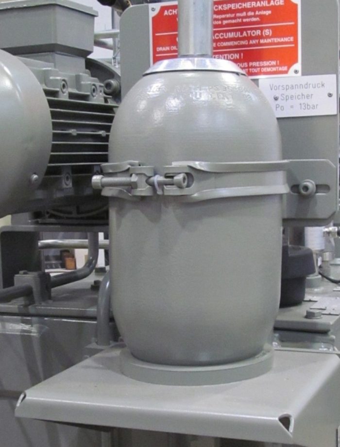
An accumulator is a steel pressure vessel with two chambers. One chamber is attached to water line or hydraulic oil hose and the other is pressurized with gas.
The sections are separated by either a flexible rubber diaphragm or a piston that slides similar to a hydraulic cylinder.
The chamber that is pressurized with gas needs to be charged for the system to work. The pressure that it is charged to is called the “charge pressure.”
As hydraulic oil enters the other side of the the bladder or piston will move toward the opposite side compressing the gas. This movement isn’t linear as the pressure increases because the gas is compressible.
What Do I Charge the Accumulator With?
Most low pressure expansion tanks used with household water systems are filled with compressed air. This is done because compressed air is readily available in most households and the pressures are relatively low 20 to 60 psi (138 to 414 kPa).
Compressed air is not the best gas for this application, Nitrogen is! Nitrogen is the most prevalent component of our atmosphere so it is easily acquired. It is inert which is great because it won’t explode like oxygen. If it leaks out, there is no risk to humans like carbon monoxide or carbon dioxide.
Nitrogen also does not contain water vapor. Standard air will have both water vapors and oxygen. This with the combination of any mold or bacteria in the air (which there is) will start a nice Petri dish in your accumulator. No one wants that.
Also, as the temperature fluctuates, the water vapor may condense giving unpredictable performance under higher pressures.
For these reasons, hydraulic accumulators are charged with nitrogen gas.
Determining Charge Pressure
Determining the charge pressure of the accumulator is the most difficult part of using an accumulator. I’ll be honest because I struggle with it as well.
Since we are dealing with compressible, non-ideal gas, the calculation below is based on empirical data and not exact. The 95% used in the equation is an efficiency rating.

Where:
- D is the discharge volume
- P1 is the accumulator charge pressure
- P2 is the discharge pressure
- P3 is the system pressure or max pressure the accumulator is charged to and
- V is the accumulator total usable volume.
Since the equation is empirical, you should always design in more accumulator capacity than what is needed. At the very least, you should be able to increase the system pressure a little.
Compression Ratio
An accumulator has a compression limit based on the physical constraints of the design. This is called compression ratio and it is defined as the system pressure / charge pressure.
For bladder accumulators, this ratio is 4:1. For piston accumulators the ratio is higher at 6:1. If exceeded, this may cause rupture to the cylinder piston or the bladder
Minimum Pressure
To prevent damage to the accumulator, we need to keep the minimum pressure at or above the charge pressure. Doing this always keeps a little bit of oil the accumulator so that the bladder or piston is not resting on the internal stops. This may or may not be a requirement based on the specific manufacturer’s requirements.
Installing the accumulator on the pressure side of a pressure compensated pump is a good way to maintain minimum pressure on the accumulator.
This requirement of the minimum pressure is for normal use only. The accumulator can handle not being pressurized for shipping and maintenance purposes.
Since we are on the topic, I should also mention that there should be a safe way to empty the accumulators of all hydraulic pressure for service. This should not be loosening a fitting and collecting the oil in a pan. (That’s dangerous)
Ok, deep breath. We’ll go a little deeper to understand this better.
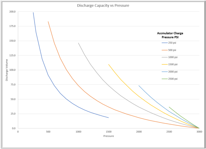
Let’s look at a plot to give a visual representation to how the accumulator behaves at multiple charge pressures. Each line is a different charge pressure and they are all capped off at the accumulator charge pressure. I chose a 1 gallon accumulator so if later you need more discharge volume you can simply scale the size of the accumulator.

Notice that all of the lines converge at the maximum pressure of the system (3000 psi). This is because in the equation, P2 equals P3 and the terms cancel out.
The curve is where the complexity in selecting a charge pressure exists to let’s do this the easy way with examples.
Expansion Tank Charge Pressure
In the case where we are protecting a system from the water hammer effect, we can add an expansion tank (small accumulator) to the line in question.
Our desire is to have lots of volume change with very little pressure change. This would be a near vertical line on the chart and the obvious selection would be a charge pressure of 250 psi.
We may even want to go with less pressure but if you do not have any charge, the volume may expand at too low of a pressure and not perform the intended duty. The other danger is that you will violate the 4:1 or 6:1 compression ratio.
Charge Pressure for Load Holding
Load holding applications are quite common and generally they don’t require very much flow because position doesn’t change. Most of your fluid loss will be from leakage internal to directional valves.
For this type of system, you will need to have a high charge pressure. Say that our application will charge the accumulator to 2500 psi and shut off the pump. Our load needs to be held at 2500 psi. (We will need a pressure reducing valve to maintain the needed pressure.)
One the graph above, if I use a 500 psi charge pressure, I can only store about 7 in3 of fluid between 2500 psi and 3000 psi. Not anywhere close enough for most requirements.
However, if I change my charge pressure to 2500 psi, I can now store about 37 in3; an incredible difference.
Now if we tweak our requirements a little, we can gain more advantage. I want to hold my load at 2000 psi. If my accumulator charge pressure is still 2000 psi but I only apply 2500 psi of hydraulic fluid to the accumulator, I increase my discharge volume.
To calculate this we will need to see what volume is available at each pressure. At 2000 psi, there is 73.2 in3; at 2500, there is 29.3 in3. The available discharge is the 43.9 in3 (73.2 – 29.3).
Determining the Charge Pressure for Low Duty Cycle Accumulators
In our roller coaster linear acceleration example above, we demonstrated how long periods of rest can be used to continuously store fluid for sudden release. The main benefit of this was smaller components and a more level loading of the system.
For these applications to be successful, you will want your function to operate at lower pressure. I recommend designing your system to be less than 50% of the system pressure. This would be no more than 1500 psi on a 3000 psi system.
For this application, you also want the charge pressure to match the functions design pressure. In the linear acceleration example, the accumulator should be charged to 1500 psi to give the best performance.
How the System Pressure Effects Volume
With a system that needs 67 gallons to perform a specific function, the system pressure before discharge is related to the size of the accumulator needed. At 1500 psi, there is 109.7 in3 available.
The table below shows what the discharge would be for an accumulator charged to 1500 psi at different operating pressures.
| Pressure (psi) | Discharge (in3 ) | Discharge Available (in3) | Size Needed (gal) |
| 2000 | 54.9 | 54.8 | 282 |
| 2500 | 21.9 | 87.8 | 176 |
| 3000 | 0 | 109.7 | 141 |
At the surface, it looks like going with a 3000 psi operating pressure makes the most sense because for 1000 psi additional pressure, I can cut my accumulator size in half. Pretty sweet.
On small systems, it probably makes sense to go with the higher pressure. However, on large systems, operating at a higher pressure may not be cost effective due to electricity and component costs.
Can I Charge to a Pressure Higher Than My System Pressure?
The short answer is No. As mentioned previously, the hydraulic pressure should always be at least the charge pressure. This is to prevent internal damage to the piston or bladder.
Since that is the case for the minimum operating pressure, it should be the same for the maximum operating pressure.
Conclusion
After analyzing three cases of accumulator usage, we have determined that accumulator charge pressure is different for each use.
Accumulators used as expansion tanks need to be charged at low pressures. Higher charge pressures are needed for situations with load holding and applications with low duty cycles will be at medium pressure.


