So there I was again; standing at a machine that I designed replacing a limit switch for the fourth time in a month. This time it would be different. This switch was used to detect the end position of a cart that rolled on rails. The limit switch had a lever with the roller on the end and was activated when a plate contacted roller.
The switch kept failing because the impact from contact was loosening the 2 screw pattern for the actuation head and eventually broke the plastic housing.
This time it was different because I was using a steel body design with 4 screws mounting the head. I haven’t serviced this switch in the nearly 2 years since. Small and seemingly un-noticable details in the switch can be the difference between years of service life.
Limit switches are an important component in almost every industrial machine. Here are a few basic pointers on selecting the right switch for your application.
Most engineers will pay attention to the body material, contact types and actuation method when selecting a limit switch. For the switch to last a long time, there must be considerations for the IP rating, wire sealing, and how the switch is mounted. Never allow water to pool against a seal.
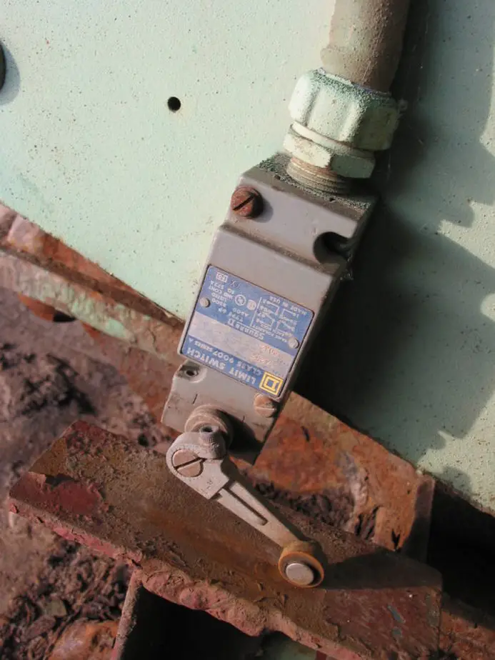
Image by John R. Southern
On a recent application, I selected a limit switch where the head was only held on by two screws. This led to repeated structural failures in the switch from the cart that was rolling by it. The long term fix was to upgrade to a switch that had the head held on with 4 screws.
1. Cycle Limit
These are mechanical switches with moving parts. They will wear out. The cycle limit is usually given by the manufacturer in millions of cycles. This is usually the number of cycles to average failure.
Find out how many cycles per day, week or year your machine will plan to see and find out how long your machine is expected to last.
Many times, you will find that the switch will outlast the machine. If not, you will want to stay well below the average cycle failure. I suggest replacing these around 75% of the estimated life and always have a spare on hand.
2. Wire Exit
An IP67 rating on the switch is all lost if your wires are not sealed correctly. There are a few things that can help you be successful here.
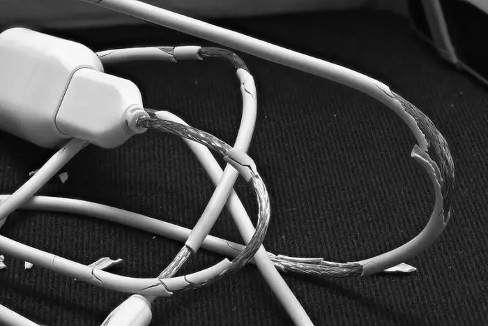
- Electrical conduit is not water tight. If you need your switch to be IP rated, don’t run the conduit right into the switch. Have a short amount of ‘exposed’ wire, but protect it with spiral wrap, split loom, or a larger diameter conduit.
- Use a sealed strain relief. Yes, if you want to maintain your IP rating, you must use sealed strain reliefs for your wires. There are many kinds available; make sure the one you select is rated for the wire diameter and the IP rating desired.
- Select NPT strain reliefs. NPT (Pipe thread) is the most common form for strain relief in electrical devices. There are other’s types of connection out there and they can be pricey. NPT offers a wide selection of conductor size and number. If preventing water intrusion is a must, be sure to seal the threads with some Teflon tape or pipe dope.
- Add droop in wire. Unless your switch is mounted vertically with with the wires pointing down, adding droop to your wire is a must.
- If there is no droop, water will gather on the wires and run down to the strain relief. Over time, water pooling on the seal will eventually get inside. This happens even with potted electronics. Adding droop prevents water from pooling near the seal.
- Never mount your switch with the wires coming out vertically upwards!
- Don’t bend the wires too quickly – When designing your wire exit, make sure that you allow plenty of room for the wire to make any turns. If the wire turns too quickly, it can lay crooked in the strain relief and not seal properly. A distance of 8-10 times the wire diameter is adequate for most applications. Consider using an angled strain relief if this is a problem.
- Beware of Multi-conductor Wires. Multi-conductor wires are difficult to seal.
- On wires with a thin jacket, there may be bumps that prevent a good seal.
- There is space between the wires where water can collect. Even if both ends are properly sealed on the jacket, cuts in the jacket along the length can allow water to intrude into the switch by means of the space between conductors.
- The best way to ensure a good seal is strip the jacket back so that only the individual conductors enter the switch. Then protect the wires from damage.
3. IP rating
An IP rating is a way to know how well an electrical device will stand up to its environment from water and other contaminates. It is not a rating of how well things like paint or other corrosion protection will hold up.
An IP number has two digits each number representing something. The first digit represents the ingress of solids into cavities. A rating of 0 is no protection and 6 will be “dust tight”.
The second number is the intrusion of liquids. The ratings for this digit go from 0 to 8. Zero is no protection from liquids. The tests get more intense as the numbers increase ending with 8 which no harmful water intrusion when immersed deeper than 1 meter.
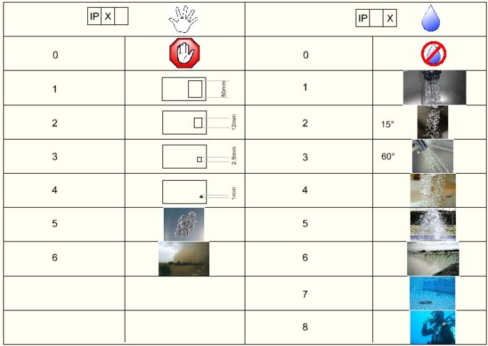
Most switches we are concerned about will fall into the range of IP65 to IP67. Here are the tests:
- IP65 – Water projected by a nozzle (6.3mm) against enclosure from any direction shall have no harmful effects.
- IP66 – Water projected in powerful jets (12.5mm nozzle) against the enclosure from any direction shall have no harmful effects.
- IP67 – Ingress of water in harmful quantity shall not be possible when the enclosure is immersed in water under defined conditions of pressure and time (up to 1 m of submersion).
For indoor applications, I recommend a minimum of IP65 unless the switch is protected from direct spray of water. For outdoor applications, I recommend an IP67 or higher switch. I would still add covers that will protect the switch from direct spray from a pressure washer.
4. Body Material
Plastic switch bodies are prevalent in the market. For your light to medium duty applications this may be adequate. Adding protection from contact and water intrusion will ensure that your switch lasts a long time.
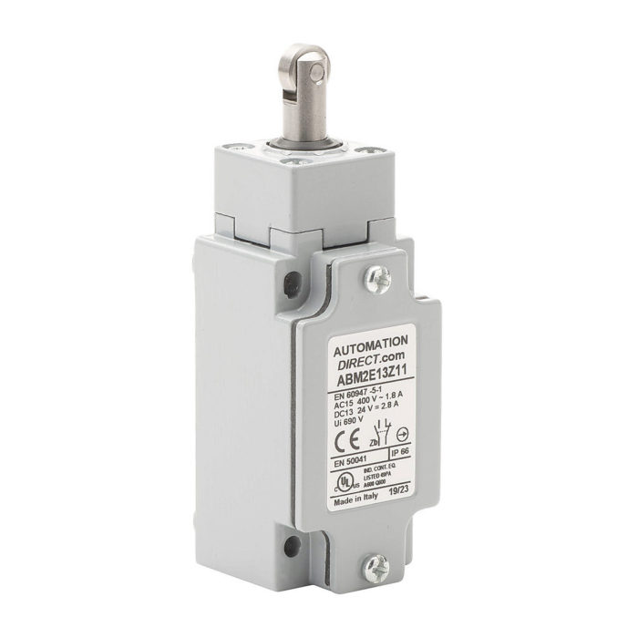
Image Courtesy of Automation Direct
Aluminum switch bodies are generally the my go to. They are robust enough to handle some misuse, but light and cost effective.
For your heavy duty applications, stainless steel is the way to go. Stainless steels are strong, weather resistant and have an excellent fatigue life. However, they will be more expensive.
Look for versions where the plunger is attached to the body with 4 screws rather than 2.
5. Contacts
Most switches come with a normally open (N.O.) and a normally closed (N.C.) set of contacts. Usually the two sets don’t use the same common wire. Some switches are available with 2 NO or 2 NC contact sets. If you need more, you can always run the signal through a relay with as many contact sets as you like.
“Fail Safe” Design
One thing to keep in mind when selecting a switch is safety when there is a failure. We always want our device to “fail safe.”
For example, if we have a rail system, but we never want the cart on it to go past a certain point we could install a switch at that point. If we wire the switch to be NO and give us a signal back when the cart is present the system will work fine.
However, if the wire has been cut, the switch will never send a signal and the cart will cruise on past the intended point. Not good!
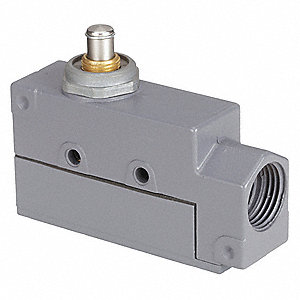
Image Courtesy of Grainger
However, with a simple change to use the normally closed signal, we will look for a high signal all the time to allow the cart to move all the time. When the cart reaches the switch, the signal will drop from high to low and signal the cart to stop.
Most importantly, if the wire is cut, the cart will think that it is at the stopping point and not move. This a fail safe! As a side benefit, the symptoms should prompt maintenance to look for cut wires and not faulty switches
6. Actuation
The super sweet thing about limit switches is that they come with a variety of actuators that can be used to sense almost any object or motion type. You should be able to find the perfect actuator for your application. Here are some of them:
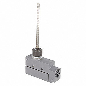
- Plungers- This is a linear pressing of the switch. You can buy these will various amounts of travel before and after the switch is activated. Some have rubber boots to protect the switch from ingesting dirt. These switches are intended to handle actuation in line with the plunger direction.
- Ball plungers – Ball plungers can handle lateral motion very well. However they are very precise and don’t handle misalignment well. These are commonly used in valve systems to determine if a valve spool has shifted. Be sure to use these will lubricants in metal to metal applications.
- Cross roller plungers – This version of a plunger has a roller mounted in it rather than a ball. They handle lateral motion very well and don’t need lubrication. As the roller diameter increases, the greater the misalignment can be.
- Rod or Wand Actuation – These are great general purpose actuators and not for precision use. It is a long stem coming out of the switch. It works much like a breakaway torque wrench does; where it builds resistance and then snaps to indicate the switch has been made. They are robust and can sense objects in and direction perpendicular to the shaft.
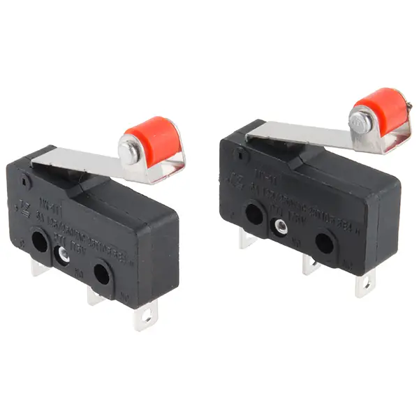
- Lever Action – These can come with or without a roller on them. Generally speaking they can be used as a plunger or a cross roller plunger. When used for lateral motion, they are good for single direction only. If ran the other way, the roller can catch and tear itself up.
- Side Rotary Action – Probably the most configurable of all the actuators. They usually have a roller mounted on the end so that there are no scratches or visible marks left on the objects. Many of the levers are adjustable in length so that you can fine tune the contact point.
SparkFun Electronics from Boulder, USA
7. Head Rotation
As already mentioned, the heads on the switches rotate and mount with screws. Only look at switches with 4 screws holding the head on. Switches with only 2 screws holding them together just aren’t strong enough for medium or heavy duty applications.
In addition to the four screws, look for switches that have tabs to further lock the head into position. The head is usually adjustable in 90° increments.
8. Mounting
On an aerial work platform that I designed, we had a “potted” PC board for controls. The way this was designed had a cover that I placed facing up. In rare situations, such as power washing, water would seep into the controls and sit on the potting.
This became an issue because the water just sat there for long periods of time; this eventually caused the board to fail.
The solution was to give water a way to exit by flipping the PCB over and drilling a small drain hole in the cover. The point here is that if water can pool on a seal, it will eventually get in.
Mounting a limit switch can be tricky. You need your mechanical action to work properly, but we also don’t want water intrusion into the switch at wire entry. To prevent this, you want the wires to enter from the bottom or side so the switch must be mounted horizontally or vertically with the actuation pointed up. If this is not the case, find a 90° strain relief for your switch or add a 90° street elbow.

You will also need to choose between tapped or through hole mounting. Many applications require using tapped holes because there is only adequate access from one side. One disadvantage is that you can cross thread or strip out the tapped hole on plastic bodies easily.
I prefer not to use this method simply because the screws needed are usually metric and I don’t have those stocked. So, it is an extra run to the store for me.
I prefer to use through hole mounting as a result. I stock equivalent sized screws and nuts. It does require another tool however.
9. Ratings
You definitely want to look for some ratings. First, most switches are UL listed. UL, Underwriters Laboratories is a non-profit group that evaluates electrical products for safety.
Second, you need to decide to select a NEMA vs IEC enclosure. International Electrotechnical Commission (IEC) enclosures are focused on lower cost and a smaller operating envelope.
NEMA enclosures are very durable and offer superior water and dust intrusion protection. Use NEMA rated enclosures for applications in harsh outdoor environments.
Conclusion
Choosing a limit switch can be a daunting task at first. I always feel lost because I don’t know what is and is not important. I hope this guide will help you get your feet wet in selecting your first switch. (Your feet may get wet, but the switch enclosure must stay dry.)

